Jun 29, 2026
Visit:14
Jun 29, 2026
Visit:14
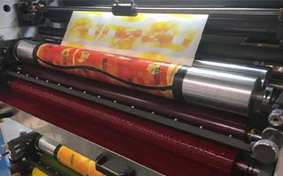
Gear marks are among the most frustrating print quality defects in flexographic printing. They appear as periodic light–dark streaks that match the gear pitch, usually spanning the full web width and running perpendicular to the web direction. These defects not only ruin the visual appeal of the printed product but also indicate mechanical issues in the drive train.
Terms like gear chatter, barring, and banding are often used interchangeably, but true gear marks have a distinct periodicity—their repeat distance precisely corresponds to the pitch circumference of a cylinder or gear. Therefore, measuring the defect spacing to identify the faulty component is the most direct and effective diagnostic approach.
This article provides a systematic troubleshooting process: measure the defect spacing, pinpoint the suspect cylinder, inspect gears, bearings, and drive components, and finally implement the right fix.
The first and most critical step is to accurately measure the repeat distance of the defects on the printed sample.
Take a printed sample showing the defect. Use a ruler or caliper to measure the straight‑line distance between two adjacent identical defects. Record this value as L.
This measured distance corresponds directly to the circumference of a rotating component—each repeat means that cylinder has completed exactly one full revolution.
Obtain the actual circumferences of the following three key cylinders:
Plate cylinder
Anilox roll
Impression cylinder
Compare your measured value L with each cylinder’s circumference. The cylinder whose circumference is closest to L is your primary suspect.
Once the suspect cylinder is identified, perform these two essential checks.
Rotate the cylinder slowly by hand and use a strong flashlight to carefully examine every tooth face on the gear:
Dried ink or foreign matter – dried ink or paper dust stuck in the tooth root causes an impact every revolution.
Burns or surface damage – burrs, pitting, or wear on the tooth profile.
Broken teeth – in severe cases, missing or chipped teeth.
Cleaning debris between teeth often resolves the issue immediately. If significant wear or broken teeth are found, the gear must be replaced.
Use a dial indicator to measure the radial runout at the cylinder shaft end:
Mount the dial indicator base on the machine frame and place the probe perpendicular to the shaft end surface.
Slowly rotate the cylinder one full turn and record the maximum and minimum readings.
The difference is the radial runout.
If the runout exceeds the manufacturer’s tolerance, the bearing is worn. Worn bearings cause radial oscillation of the cylinder, which appears on the print as wide, blurred bands with a spacing slightly larger than the cylinder circumference.
If the gear teeth and bearings check out, the problem may lie further upstream in the drive train.
Check the coupling between the motor and the cylinder:
Cracked or aged rubber elements – flexible couplings with deteriorated rubber lose their damping and compensation capability, leading to uneven torque transmission.
Worn keyways – worn keyways create backlash, allowing relative motion between the cylinder and its drive shaft.
Rotate the cylinder by hand and feel for abnormal “lost motion” or looseness. Replace the coupling if noticeable wear is found.
For systems using timing belts:
Inspect for missing teeth or worn tooth profiles.
Check belt tension – significant slack can cause tooth jumping, resulting in irregular defect spacing.
| Defect Appearance | Spacing Characteristic | Likely Cause |
|---|---|---|
| Sharp, distinct lines | Equal to gear pitch | Damaged tooth, broken tooth, or foreign matter between teeth |
| Wide, blurred bands | Slightly larger than cylinder circumference | Bearing wear causing cylinder runout |
| Irregular spacing | Varies | Coupling wear or timing belt slippage |
If the defect spacing does not match any cylinder circumference, or if the spacing is inconsistent and intermittent, suspect the drive coupling or timing belt first.
While waiting for replacement parts, the following temporary measures can help complete urgent jobs:
Slightly increase printing pressure – additional nip pressure can partially mask minor gear marks.
Use a softer mounting tape – softer cushion tape can absorb some vibration, reducing defect visibility.
Reduce press speed – lower speeds often reduce vibration amplitude.
Note: These are only temporary fixes. Prolonged use accelerates wear and should not be adopted as regular practice.
The definitive solution depends on your diagnosis:
Gear damage → Replace the damaged gear.
Bearing wear → Replace the bearings.
Coupling aging → Replace the rubber element or the entire coupling.
Timing belt issues → Replace the belt and re‑tension properly.
The best strategy to prevent gear marks is a systematic maintenance program:
1. Prevent foreign matter from entering gears
Establish an SOP ensuring gear guards remain closed during operation. Regularly clean ink residue and paper dust from gear housings.
2. Regularly check gear lubrication
Use the specified gear grease and follow the recommended relubrication schedule.
Check for grease degradation, emulsification, or contamination by ink.
Insufficient lubrication accelerates gear wear, increases backlash, and promotes gear marks.
3. Establish periodic inspection routines
Inspect critical gear teeth monthly.
Measure cylinder radial runout quarterly and track trends.
Check couplings and timing belts semi‑annually.
4. Consider equipment upgrades
If gear marks recur despite thorough maintenance, consider:
Switching to helical gears instead of spur gears for smoother operation.
Evaluating an upgrade to servo drives – while they do not eliminate all mechanical issues, they reduce the number of gears in the drive train.
Yes. Gear marks may be more pronounced at specific speeds due to resonance. If the defect is severe within a certain speed range but diminishes elsewhere, there is likely a resonance point. Try avoiding that speed range and check for loose components that may need tightening.
Yes. Solid areas are the most sensitive to ink film variations, so gear marks are most obvious there. In screens and gradients, they may appear as density fluctuations or dot distortion. Always inspect solid colour patches when evaluating samples.
Servo drives can eliminate gear marks originating from mechanical gear trains because each printing unit is directly driven, reducing the number of gears in the transmission. However, servo drives do not eliminate all periodic defects—bearing wear, cylinder runout, and coupling problems can still produce similar print defects. Therefore, routine mechanical maintenance remains essential even on servo‑driven presses.
Troubleshooting gear marks follows a clear logical chain:
Measure defect spacing → pinpoint the suspect cylinder.
Inspect gear teeth → clean debris or replace gears.
Measure bearing runout → replace worn bearings.
Inspect drive components → replace couplings or belts.
Implement preventive maintenance → establish regular inspection schedules.
Following this step‑by‑step process will resolve the vast majority of gear mark issues. If all mechanical checks are completed and the problem persists, advanced diagnostics such as vibration analysis may be required to detect abnormal frequency components in the machine’s operation.
Need advanced diagnostic support? If your press still shows gear marks after thorough mechanical inspection, we offer professional vibration analysis and condition monitoring services. Contact us for more information.
Jun 29, 2026
Jun 11, 2026
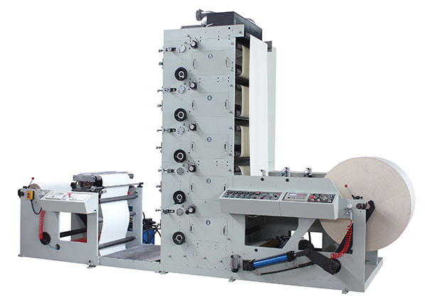
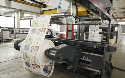
FLEXO PRINTING MACHINE
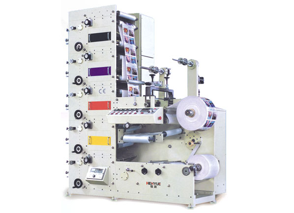
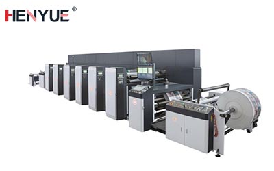
FLEXO PRINTING MACHINE
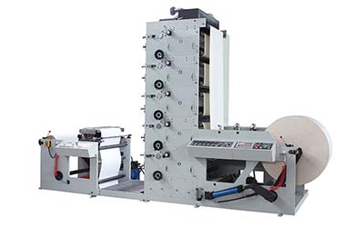
FLEXO PRINTING MACHINE
GET A QUOTE