
 English
 Español
 Jul 17, 2026
Visit:5
Jul 17, 2026
Visit:5
Register marks are the “eyes” of the automatic registration system in CI flexo printing. They tell the sensors where each color plate is, allowing the system to adjust register between color stations in real time. However, improper mark placement or poor design can cause sensor misreading, registration errors, longer setup times, material waste, and even scrapped batches.
This guide is written for prepress operators and production planners. It provides recommended placement, size specifications, and background requirements for register marks on flexo plates, helping you prevent registration issues at the source.
Before discussing where to place marks, it is important to understand how the sensors read them.
Automatic register systems on CI flexo presses rely on optical sensors to detect marks printed on the substrate. Each sensor has a fixed field of view and a focal plane – it must be at a specific distance and angle to clearly “see” the mark.

The sensor’s field of view is usually defined by an aperture in an optical mask, limiting the actual area the sensor can detect. This means:
The mark must fall within the sensor’s detection range;
The area around the mark must be clean, with no other printed elements that could interfere with recognition.
Modern sensors can detect extremely low‑contrast marks, including metallic inks, UV inks, and nearly transparent varnishes. Nevertheless, a clear mark and a clean background remain the prerequisites for reliable reading.
CI flexo register systems typically need to detect deviations in two directions:
Longitudinal (MD) marks – used to detect positional errors in the circumferential direction. They help the system adjust circumferential register between colors.
Lateral (CD) marks – used to detect errors in the axial direction. They help the system adjust axial register.
In practice, the most common mark shape is the crosshair – one line parallel to the machine direction and one perpendicular to it. A single mark provides both longitudinal and lateral reference.
Where you place the mark on the plate directly affects how reliably the sensor can read it.
Register marks should be placed at the start of the repeat length, typically close to the plate gap. This is because:
The sensor reads the mark at the beginning of each repeat cycle, allowing the system to make corrections within each cycle;
Being near the gap means the mark lies in a relatively stable area of the plate, reducing the effect of plate deformation.
For long production runs, it is advisable to place register marks in every repeat length. In multi‑color printing, all color plates must have their marks at the same position within the repeat length – otherwise the sensor cannot compare them correctly.
Keep the mark edge at least 10–15 mm away from the nearest printed graphic.
This is the most overlooked rule and also the most common cause of problems. If the mark is too close to graphics, the sensor’s field of view may pick up pattern elements, causing misreading. The sensor cannot distinguish the mark from the pattern, and the register system will apply incorrect corrections.
No other printed elements should appear within 5 mm of the mark’s edge.
This “clearance zone” ensures that the sensor’s field of view contains only the mark itself. Any lines, blocks, or text entering this zone can be misinterpreted as part of the mark.
In practice, it is wise to make the clearance zone larger than 5 mm to provide a safety margin. Especially with complex designs, always verify that the area around the mark is clean on all color plates.
The design of the mark itself is equally critical – size, line width, orientation, and colour all affect sensor recognition.
A standard crosshair is recommended as the register mark. Specifications:
| Parameter | Recommended Value |
|---|---|
| Line width | 0.5 – 1.0 mm |
| Overall crosshair length | 10 – 15 mm |
Too fine a line may break or become unclear during printing, making it unreadable; too thick a line reduces positioning accuracy. The length should be sufficient for the sensor to easily locate the intersection point within its field of view.
The two lines of the crosshair should be parallel and perpendicular to the machine direction, respectively.
The MD‑parallel line detects lateral errors;
The MD‑perpendicular line detects longitudinal errors.
This standard orientation allows the register system’s algorithms to interpret the mark’s position directly, without additional coordinate transformation.
Use a colour that provides high contrast with the substrate and surrounding graphics.
First choice: Black
Second choice: Magenta or other dark colours
Avoid: colours that are close to the substrate colour or that blend into adjacent patterns
The sensor’s primary task is to detect the contrast difference between the mark and its background. If the mark colour is too similar to the background, the sensor may not reliably identify the mark position.
In multi‑colour printing, it is common to print the register mark in the colour of the first printing unit, or to use a dedicated spot colour for registration.
Clear films are common substrates in CI flexo printing, but they present a particular challenge for register marks.
On clear films, a white backing patch must be printed underneath the register mark.
Clear film is transparent; the optical sensor’s light passes through, preventing sufficient reflected contrast to recognise the mark. The white patch provides an opaque reflective background that allows the sensor to see the mark clearly.
The white patch should be 5–10 mm larger than the register mark.
This size ensures that even with slight register variations, the mark remains fully within the white patch and does not partially “run off” into the transparent area. The patch should be printed with high‑opacity white ink to ensure complete opacity.
The following are the most frequent register‑mark errors in prepress:
The mark edge is less than 10 mm from the nearest pattern, so the sensor’s field of view picks up other printed elements, causing misreading.
Solution: Reserve sufficient mark area during design, and ensure at least 10–15 mm clearance on all colour plates.
The mark colour is too similar to the substrate or adjacent patterns, making it unreliable for the sensor.
Solution: Use black or dark marks; use dark marks on light substrates, and on dark substrates use a white patch + dark mark.
The sensor light passes through the transparent film, no reflective contrast is formed, and the mark “disappears”.
Solution: When printing register marks on clear film, always add a white patch underneath, 5–10 mm larger than the mark.
Different colour plates have their register marks at different positions within the repeat length, so the sensor cannot compare them correctly.
Solution: All colour plates must have their marks at exactly the same repeat‑length position.
Yes, provided that the repeat length, plate size, and printing conditions are the same for each job. If the repeat length changes, the absolute position of the mark on the plate will vary, but the relative principles apply to all jobs.
If the sensor cannot find the mark, the automatic register system will be unable to function. The operator needs to:
Stop and check whether the mark is printed clearly;
Check for interfering elements around the mark;
Clean the sensor lens;
Verify sufficient contrast between the mark colour and background.
In severe cases, re‑making the plate or adjusting plate mounting may be necessary.
Yes. The repeatability of sleeve mounting directly affects the consistency of register mark positions. The cumulative thickness tolerances of sleeve + tape + plate directly affect the printed repeat length. High‑quality sleeve mounting systems combined with camera‑assisted positioning can achieve tens‑of‑microns repeatability. Recommendations:
Use high‑precision sleeves and mounting tapes;
Employ video‑ or laser‑assisted plate mounting systems;
Regularly check sleeve concentricity and run‑out tolerances.
Proper register mark placement is the first line of defence for registration accuracy in CI flexo printing. Before sending plate files for imaging, check each item below:
| Check Item |
|---|
| ☐ Mark placed at the start of the repeat length |
| ☐ Mark edge ≥ 10‑15 mm from nearest graphic |
| ☐ No printed elements within 5 mm around the mark |
| ☐ Crosshair line width 0.5‑1.0 mm, overall length 10‑15 mm |
| ☐ Crosshair orientation parallel/perpendicular to MD |
| ☐ Mark colour has sufficient contrast with background |
| ☐ White patch added on clear film |
| ☐ Mark position consistent across all colour plates |
Need your prepress files checked for register mark compliance? Contact us for a prepress audit service.

Jul 17, 2026

Jun 30, 2026

FLEXO PRINTING MACHINE
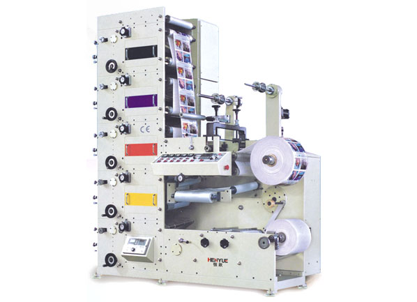
FLEXO PRINTING MACHINE
FLEXO PRINTING MACHINE
GET A QUOTE